

Rebar Basics
Rebar Spacing: How It Gets Determined
Spacing is not a rule of thumb — it comes out of the structural design. What sets it, what the field is allowed to change, and the failure that happens after the inspection passes.
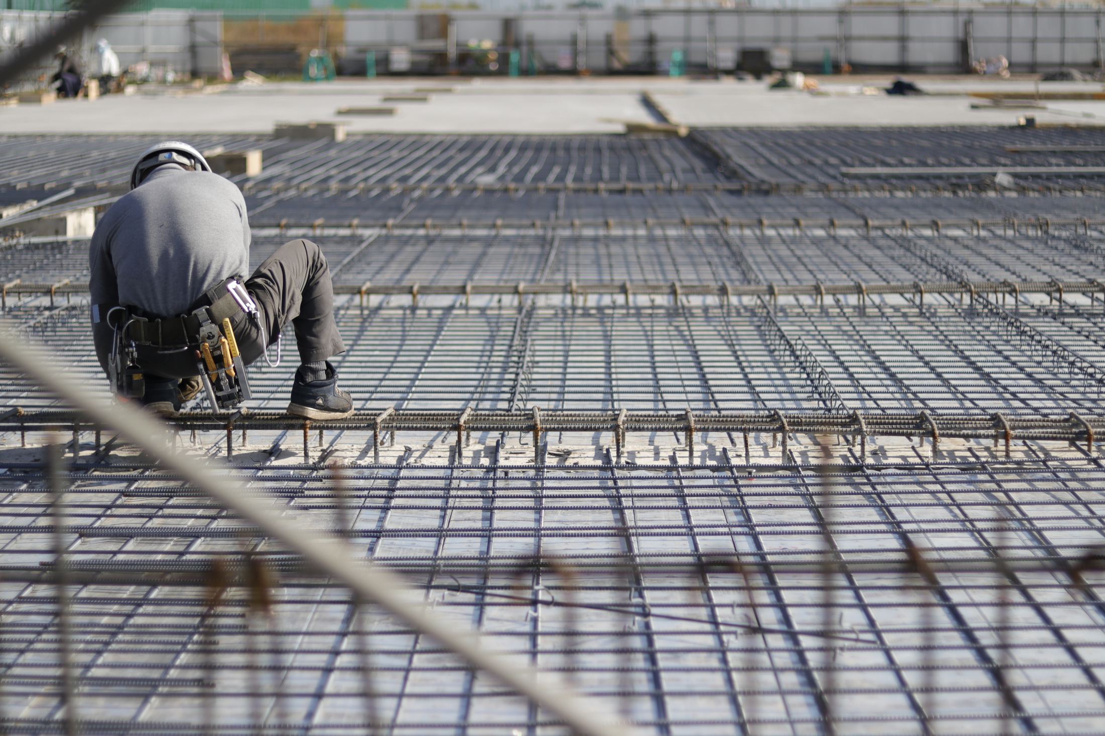
People look for a number — twelve inches on centre, eighteen on centre — and there is no universal one. Spacing falls out of the structural engineer's calculation for that element, and the drawing is the answer.
That is worth stating plainly because spacing is the reinforcement property most often assumed rather than read. A crew that has placed a hundred slabs at twelve inches will place the hundred-and-first at twelve inches unless something stops them, and on the job where it should have been eight, nothing will look wrong until it is a core sample.
What actually sets the spacing
The engineer picks a bar size and a spacing together to deliver a required area of steel per foot of element. Get the same area with fewer large bars or more small ones, and the choice between them comes down to congestion, cover and constructability.
- Load and span. More demand means more steel area, which means bigger bar, tighter spacing, or both.
- Crack control. Distributing the same area over more, smaller bars at closer spacing gives finer crack distribution.
- Code minimums and maximums. There are limits on both ends — bars far enough apart for concrete and aggregate to flow between them, and close enough to act as distributed reinforcement.
- Congestion. At intersections, splices and embeds, theoretical spacing has to survive contact with everything else in the element.
The crack-control point is the one most often missed by people reading a drawing for the first time, and it explains a lot of otherwise puzzling details.
Reinforced concrete cracks — that is designed, not a defect. What design controls is crack width, because wide cracks let water and chlorides reach the bar and compromise cover. For a given total area of steel, many small bars at close spacing produce many fine cracks; few large bars at wide spacing produce fewer, wider ones. The total steel is identical and the durability outcome is not.
That is why a slab in an aggressive exposure is often detailed with smaller bar at closer spacing than the strength calculation alone would need. The spacing is doing durability work.
The two hard limits
Minimum spacing exists so concrete can physically get around the bar. Fresh concrete has aggregate in it, and that aggregate has to pass between bars and be vibrated into place. The limit is set by bar diameter and by the largest aggregate in the mix, and it is the reason a detail that satisfies the structural calculation can still be unbuildable.
This is the failure that produces honeycombing — voids where concrete bridged across closely spaced bars instead of flowing between them. A void at a congested joint is a structural defect at the worst possible location, and it is not visible until the forms come off.
Maximum spacing exists so the reinforcement behaves as a distributed system rather than a few isolated bars. Beyond a certain spacing the concrete between bars is effectively unreinforced, cracks open wide between them, and the steel stops doing the crack-control job it was partly there for.
Both limits are code requirements, both appear on the drawing implicitly rather than explicitly, and both are reasons a field adjustment can be wrong even when it looks reasonable.
Spacing, size and the trade a detailer makes
Because area is what matters, a detailer or engineer has a genuine choice: the same square inches per foot can come from #4 at close spacing or #6 at wide spacing.
Fewer, larger bars mean fewer pieces to place, fewer ties, faster placement and heavier lifts — and more congestion at splices, since a lap in large bar takes more room. More, smaller bars mean finer crack control, easier handling and more labour per ton.
Bar size and spacing are therefore a single decision, not two, and a package priced on tonnage without reading which way that decision went has not been priced properly.
What the field may and may not adjust
A crew can shift a bar to clear a conduit or an embed, within the tolerance the drawings allow. A crew cannot change the spacing because the layout came up short at the end of a run. That is a question for the engineer, and it is faster to ask it than to place a run and take it out.
The most common real-world failure is not wrong spacing on paper. It is correct spacing that drifted during the pour because the supports and ties were not adequate — the steel was right when it was inspected and wrong when the concrete went around it.
The second sentence is the important one and deserves its own emphasis, because it is the failure mode nobody photographs.
A mat is tied, inspected and signed off. Then it is walked on for six hours by a placing crew, a pump hose is dragged across it, vibrators go into it, and a power screed runs over it. If the ties are doing structural work — holding the cage square — and the supports are at adequate spacing, the geometry survives. If they are not, bars slide, mats rack, and the spacing in the finished element is not the spacing the inspector approved.
Nothing about the finished slab reveals it. That is the whole problem with spacing failures: they are invisible, they passed inspection, and they are found by a scan or a core years later.
Where spacing gets decided in practice
The drawing is the answer, but the drawing has to be readable at six in the morning. Spacing called out per element, on the sheet the crew is holding, prevents the specific failure of a crew inferring spacing from a section cut on another sheet or from what they did yesterday.
Conflicts are the other half. Where a bar genuinely cannot sit at its spacing because a sleeve or embed occupies the position, the resolution belongs in the submittal with an engineer's answer attached, not on the deck. A field resolution to a spacing conflict is a design change made by whoever was standing there.
The placement sequence matters too, because spacing in a congested element depends on what went in first. Bars that can be threaded into position in one order cannot in another, and a crew forced to work backwards will open spacing to make steel fit.
The practical version
Spacing is a design output, cover is a tolerance, and support is what preserves both. A crew that treats the third one as optional will hand you an element that passed inspection and still does not match its drawing.
If you want the spacing and congestion on a set looked at before it is fabricated rather than after, that is a conversation worth having.